Digital Wood Carver
DWC Engineering Reference Library

DWC MK3/4 Controller Reference

PlanetCNC MK3/4 board headers, screw terminals, IDC26 header, and DWC2440 usage standards

Revision: 2.0 Document: DWC-MK34-REF-001 Assembly • Service • Engineering

Used On DWC Machines

Current and legacy MK3/4 controller platform assignments.

Machine / Platform Controller Status
DWC2440 PlanetCNC MK3/4 Current production controller platform
Legacy DWC2636 PlanetCNC MK3/4 Older legacy commercial units
Legacy DWC3648 PlanetCNC MK3/4 Older legacy commercial units
Legacy DWC4848 PlanetCNC MK3/4 Older legacy commercial units
Legacy DWC5100 PlanetCNC MK3/4 Older legacy commercial units
DWC Controller Matrix: DWC1824 uses MK3DRV. DWC2440 uses MK3/4. Current DWC2636, DWC3648, DWC4848, and DWC5100 systems use MK3. Some older legacy commercial machines used MK3/4.

MK3/4 Controller Board Overview

Connector locations and board identification.

MK3/4 controller board overview

MK3/4 26-Pin IDC Header

Dedicated reference for the IDC26 header and core motion/control signals.

MK3/4 26-pin IDC header
Signal Group Signals Use
Axis 1STEP1, DIR1Motion output to external driver
Axis 2STEP2, DIR2Motion output to external driver
Axis 3STEP3, DIR3Motion output to external driver
Axis 4STEP4, DIR4Motion output to external driver
EnableENAExternal driver enable reference
LimitsLIM1, LIM2, LIM3Limit/home input references
SafetyE-STOPEmergency stop reference
I/OIN1, OUT1, OUT2, OUT6Machine input/output references
Power/CommonGND, NC/+5VLogic reference / common
DWC Note: The 26-pin IDC header is important on MK3/4-based DWC machines because it can carry step/direction, enable, limit, E-stop, input, and output signals through one connector.

MK3/4 Axis Connector

Axis output connector for external stepper drivers.

MK3/4 Axis Connector
Signal Function Notes
+5V Logic power reference Axis output IDC header
ERROR Driver error input reference External driver feedback
STEP Step pulse signal To DM556 / external stepper driver
DIR Direction signal To DM556 / external stepper driver
ENABLE Driver enable signal External driver enable
GND Ground reference Signal common
DWC2440: Axis outputs are used with external DM556 stepper drivers.

MK3/4 Input Connector

Screw terminal input connector.

MK3/4 Input Connector
Signal Function Notes
IN1 Machine input 1 Machine-specific input
IN2 Machine input 2 Machine-specific input
IN3 Machine input 3 Machine-specific input
IN4 Machine input 4 Machine-specific input
GND Ground reference Input common

MK3/4 Output Connector

Screw terminal output connector.

MK3/4 Output Connector
Signal Function Notes
OUT1 Machine output 1 Common spindle/router control reference
OUT2 Machine output 2 Machine-specific output
OUT6 Output / speed reference Machine-specific use
GND Ground reference Output common
+5V Logic power reference Output connector

MK3/4 Limit Connector

Limit/home switch screw terminal connector.

MK3/4 Limit Connector
Signal Function Notes
LIMIT 1 Limit input 1 Machine-specific assignment
LIMIT 2 Limit input 2 Machine-specific assignment
LIMIT 3 Limit input 3 Machine-specific assignment
LIMIT 4 Limit input 4 Machine-specific assignment
GND Ground reference Limit common

MK3/4 CTRL Connector

Control connector for E-stop, index, and encoder references.

MK3/4 CTRL Connector
Signal Function Notes
E-STOP Emergency stop input Control/safety reference
IDX Index input Spindle/encoder/index reference
ENC A Encoder A channel Encoder reference
ENC B Encoder B channel Encoder reference
GND Ground reference CTRL common

MK3/4 JOG Connector

Jog header for pendants, MPG controls, and external operator stations.

MK3/4 JOG Connector
Signal Function Notes
JOG 1–8 Jog input references Pendant / operator control
POT Potentiometer input reference Jog/feed control use
+3.3V Logic reference voltage JOG header
ALT1 / ALT2 Alternate function inputs JOG header
SHIFT Shift input reference JOG header
GND Ground reference JOG common

DWC2440 Jog Pendant Wiring

Membrane jog buttons and 5kΩ potentiometer wiring to the MK3/4 JOG header.

Pendant Cable & Function Overview

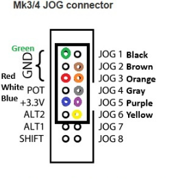
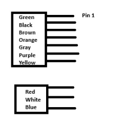
10-conductor pendant cable reference.
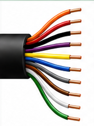
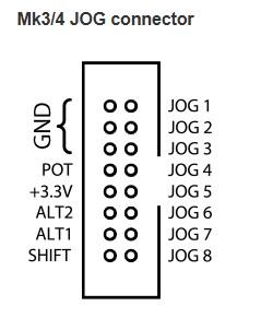
DWC2440 jog pendant 10-conductor wire
Wire Color Function MK3/4 JOG Header
OrangeY+ JogJOG3
RedPotentiometer GroundGND
BlackX+ JogJOG1
PurpleZ+ JogJOG5
YellowZ− JogJOG6
BluePotentiometer Reference+3.3V
GrayY− JogJOG4
BrownX− JogJOG2
WhitePotentiometer SignalPOT
GreenCommon GroundGND
DWC Standard: JOG7 and JOG8 are not used on the DWC2440 jog pendant.

MK3/4 JOG Header Mapping

DWC2440 pendant implementation.

MK3/4 JOG header DWC2440 mapping
MK3/4 Pin DWC2440 Function Wire Color
JOG1X+Black
JOG2X−Brown
JOG3Y+Orange
JOG4Y−Gray
JOG5Z+Purple
JOG6Z−Yellow
JOG7Not Used
JOG8Not Used
POTFeed Override SignalWhite
+3.3VPotentiometer ReferenceBlue
GNDCommon / Pot GroundGreen / Red

DWC2440 Pendant Membrane & 5kΩ Potentiometer

Jog membrane and feed override reference.

DWC2440 pendant membrane and potentiometer wiring
Device Connection Purpose
MembraneJOG1–JOG6 + GNDX+, X−, Y+, Y−, Z+, Z− jog controls
5kΩ POTRed → GNDPotentiometer ground
5kΩ POTWhite → POTFeed override signal
5kΩ POTBlue → +3.3VPotentiometer reference voltage
Service Note: If a jog direction does not respond, check the matching JOG wire and membrane continuity. If feed override does not respond, verify Red to GND, White to POT, Blue to +3.3V, and confirm the 5kΩ potentiometer operation.

DWC2440 Motion Control Architecture

How the MK3/4 controller fits into the DWC2440 motion system.

MK3/4 Controller
Motion command source
Axis / IDC Output
Step, direction, enable
DM556 Driver
External stepper driver
Axis Motor
X, Y, Z, A
DWC2440: The MK3/4 controller is paired with external DM556 stepper drivers for the X, Y, Z, and A axes. Driver DIP switch settings are machine-specific and should be documented in the DWC2440 Control Box Reference.

DM556 Stepper Driver Overview

DWC2440 external motor driver reference.

DM556 stepper driver
Item Reference Notes
DriverDM556 Microstep DriverUsed with DWC2440 external driver architecture
ControlPUL+, PUL−, DIR+, DIR−, ENA+, ENA−Step, direction, and enable control signals
MotorA+, A−, B+, B−Stepper motor phase outputs
Power+V, GNDDriver DC power input
DIP SwitchesSW1–SW8Current and microstep settings
Important: DWC2440 driver DIP switch settings are production data and should be documented in the DWC2440 Control Box Reference.

Expansion Interfaces

CAN and EXT connector references.

CAN Connector

MK3/4 CAN connector
SignalFunctionNotes
CANH CAN bus high Expansion communication
CANL CAN bus low Expansion communication
+5V Logic power reference CAN connector
GND Ground reference CAN connector

EXT Connector

MK3/4 EXT connector
SignalFunctionNotes
CLK Clock Expansion header
MISO SPI MISO Expansion header
SCL I2C clock Expansion header
TX Serial transmit Expansion header
+5V Logic power reference Expansion header
SSEL SPI select Expansion header
MOSI SPI MOSI Expansion header
SDA I2C data Expansion header
RX Serial receive Expansion header
GND Ground reference Expansion header

Official Documentation & Resources

Manufacturer resources and DWC support references.

Disconnect power before working on controller wiring. Verify board orientation, terminal labeling, and machine-specific documentation before making wiring changes.