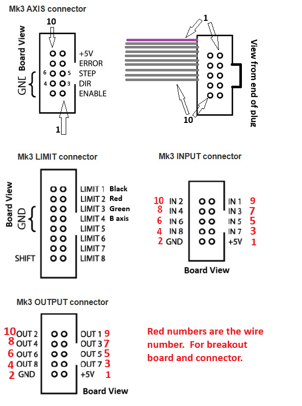
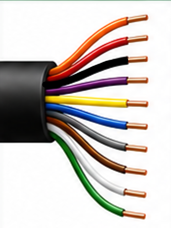
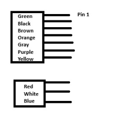
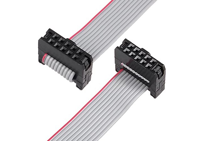
10-Pin Ribbon Cable
IDC cable reference.
PlanetCNC MK3 board headers, connector pinouts, ribbon cable numbering, and DWC usage standards
Current MK3 controller platform assignments.
| Machine / Platform | Controller | Status |
|---|---|---|
| DWC2636 | PlanetCNC MK3 | Current commercial controller platform |
| DWC3648 | PlanetCNC MK3 | Current commercial controller platform |
| DWC4848 | PlanetCNC MK3 | Current commercial controller platform |
| DWC5100 | PlanetCNC MK3 | Current commercial controller platform |
Header locations and connector identification.
Wire #1 is the pink/red stripe conductor.
IDC cable reference.
Board view and connector wire numbering.
Board-view signal mapping to 10-pin ribbon wire numbers.
| Item | Signal / Function | Notes |
|---|---|---|
| 1 | +5V | Logic power reference |
| 2 | GND | Ground |
| 3 | IN7 | Input 7 |
| 4 | IN8 | Input 8 |
| 5 | IN5 | Tool Present Sensor on ATC references |
| 6 | IN6 | Carousel Home on DWC2636 / DWC3648 |
| 7 | IN3 | Fixed Tool Length Measure Sensor |
| 8 | IN4 | Tool Clamp Sensor |
| 9 | IN1 | Digital Probe accessory on DWC2636 / DWC3648 |
| 10 | IN2 | Touch Plate / Puck |
Output header mapping based on the DWC ribbon numbering standard.
| Item | Signal / Function | Notes |
|---|---|---|
| 1 | +5V | Logic power reference |
| 2 | GND | Ground |
| 3 | OUT7 | Tool Clamp Release / Tool Release Solenoid |
| 4 | OUT8 | Dust Blow-Off / Dust Removal Solenoid |
| 5 | OUT5 | Dust Brush / Dust Hood Lift |
| 6 | OUT6 | 0–5V Spindle Speed |
| 7 | OUT3 | Rack Move on Pneumatic Rack ATC / unassigned on Carousel ATC |
| 8 | OUT4 | Output 4 |
| 9 | OUT1 | Spindle On / Off |
| 10 | OUT2 | Laser PWM |
Limit connector reference and DWC machine usage conventions.
| Item | Signal / Function | Notes |
|---|---|---|
| LIMIT 1 | Z+ | DWC2636 / DWC3648 and DWC4848 / DWC5100 assignment |
| LIMIT 2 | X− | DWC2636 / DWC3648 and DWC4848 / DWC5100 assignment |
| LIMIT 3 | Y− | DWC2636 / DWC3648 and DWC4848 / DWC5100 assignment |
| LIMIT 4 | B− | Carousel ATC home / B-axis reference |
| LIMIT 5 | Reserved | Future use |
| LIMIT 6 | Reserved | Future use |
| LIMIT 7 | Reserved | Future use |
| LIMIT 8 | Reserved | Future use |
Control header pinout for E-stop, mode inputs, axis select, enable, and index references.
| Item | Signal / Function | Notes |
|---|---|---|
| E-STOP | Emergency stop input reference | CTRL header |
| MD1 / MD2 | Mode input references | CTRL header |
| AX1 / AX2 | Axis select references | CTRL header |
| EN1A / EN1B | Enable input references | CTRL header |
| IDX | Index input reference | CTRL header |
| +5V / GND | Logic reference power and ground | CTRL header |
Jog header pinout for external jog controls, pendants, and future control accessories.
| Item | Signal / Function | Notes |
|---|---|---|
| JOG 1–8 | Jog input references | JOG header |
| POT | Potentiometer input reference | JOG header |
| +3.3V | Logic reference voltage | JOG header |
| ALT1 / ALT2 | Alternate function inputs | JOG header |
| SHIFT | Shift input reference | JOG header |
| GND | Ground reference | JOG header |
Standard DWC pendant wiring for MK3 and MK3/4 JOG header systems.
10-conductor pendant cable reference.
| Wire Color | Function | MK3 JOG Header |
|---|---|---|
| Orange | Y+ Jog | JOG3 |
| Red | Potentiometer Ground | GND |
| Black | X+ Jog | JOG1 |
| Purple | Z+ Jog | JOG5 |
| Yellow | Z− Jog | JOG6 |
| Blue | Potentiometer Reference | +3.3V |
| Gray | Y− Jog | JOG4 |
| Brown | X− Jog | JOG2 |
| White | Potentiometer Signal | POT |
| Green | Common Ground | GND |
DWC pendant implementation.
| MK3 Pin | DWC Function | Wire Color |
|---|---|---|
| JOG1 | X+ | Black |
| JOG2 | X− | Brown |
| JOG3 | Y+ | Orange |
| JOG4 | Y− | Gray |
| JOG5 | Z+ | Purple |
| JOG6 | Z− | Yellow |
| JOG7 | Not Used | — |
| JOG8 | Not Used | — |
| POT | Feed Override Signal | White |
| +3.3V | Potentiometer Reference | Blue |
| GND | Common / Pot Ground | Green / Red |
Jog membrane and feed override reference.
| Device | Connection | Purpose |
|---|---|---|
| Membrane | JOG1–JOG6 + GND | X+, X−, Y+, Y−, Z+, Z− jog controls |
| 5kΩ POT | Red → GND | Potentiometer ground |
| 5kΩ POT | White → POT | Feed override signal |
| 5kΩ POT | Blue → +3.3V | Potentiometer reference voltage |
Axis connector pinout for motor driver wiring.
| Item | Signal / Function | Notes |
|---|---|---|
| +5V | Logic power reference | Axis header |
| ERROR | Driver error input reference | Axis header |
| STEP | Step pulse signal to motor driver | Axis header |
| DIR | Direction signal to motor driver | Axis header |
| ENABLE | Driver enable signal | Axis header |
| GND | Ground reference | Axis header |
Manufacturer resources and DWC support references.