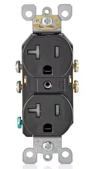
Main Power Input
120VAC single phase / 15A system
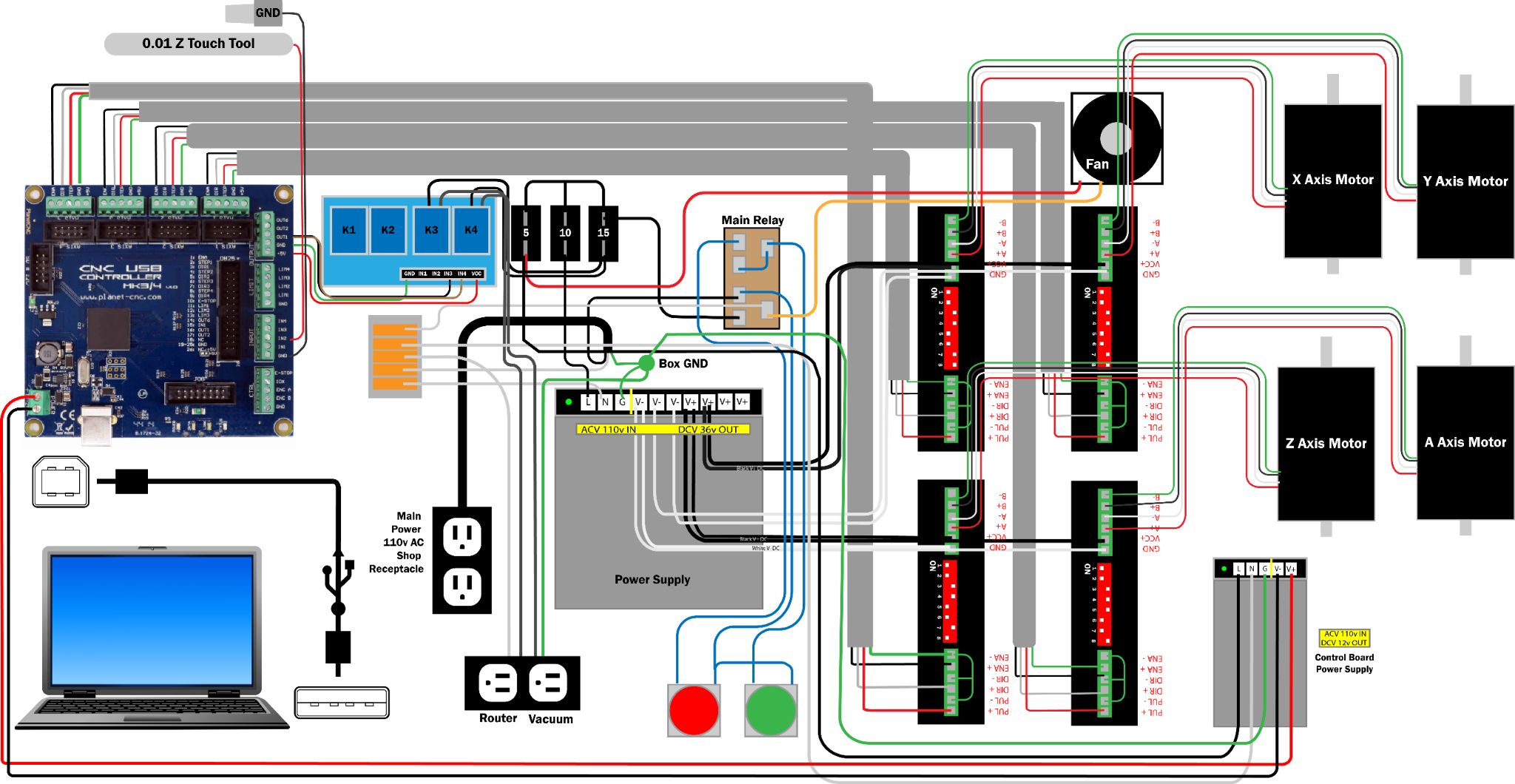
| Conductor | Wire | Connection |
|---|---|---|
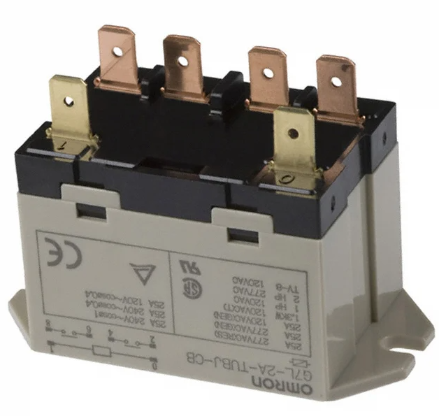
| Hot | Black 12 AWG | Omron G7L rear #2 spade |
| Neutral | White 12 AWG | WAGO 221 neutral hub |
| Ground | Green 12 AWG | Control box ground lug bolt |
DWC Standard: DWC2440 control box uses a 12/3 power cord and 120VAC single-phase power.