Machine Compatibility
Pneumatic Rack ATC configuration.
| Item | Assignment | Notes |
|---|---|---|
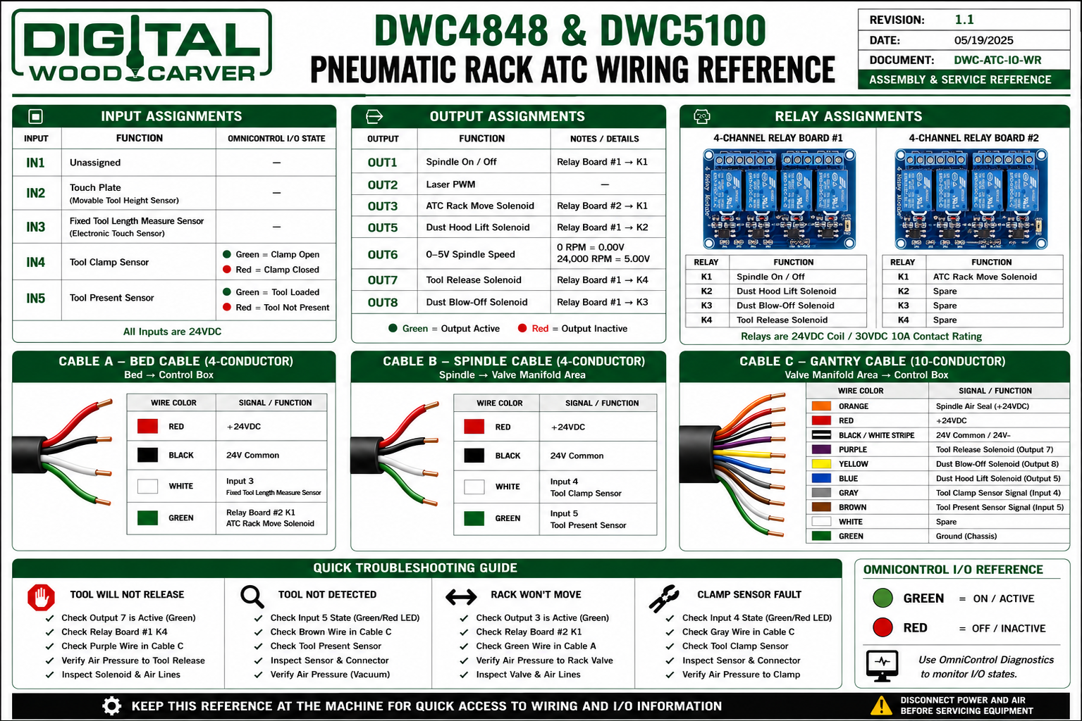
| Machines | DWC4848 / DWC5100 | Pneumatic Rack ATC configuration |
| Controller | PlanetCNC MK3 | Current commercial controller platform |
| ATC Type | Pneumatic Rack | Rack move output uses Relay Board #2 K1 |
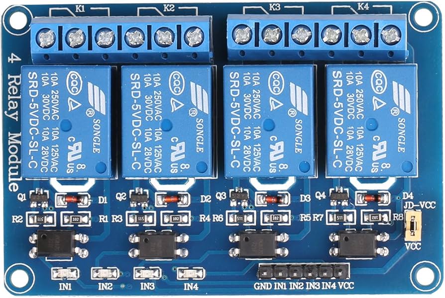
| Relay Boards | Two 4-channel relay boards | Board #1 and Board #2 |
| Cable A | Bed Cable | 4-conductor cable to control box |
| Cable B | Spindle Cable | 4-conductor cable to valve manifold |
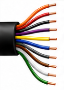
| Cable C | Gantry Cable | 10-conductor cable to control box |