Machine Compatibility
Carousel ATC configuration.
| Item | Assignment | Notes |
|---|---|---|
| Machines | DWC2636 / DWC3648 | Carousel ATC configuration |
| Controller | PlanetCNC MK3 | Current commercial controller platform |
| ATC Type | Carousel | Carousel axis is B |
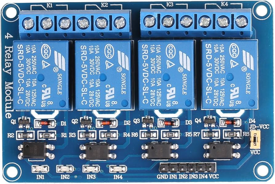
| Relay Boards | One 4-channel relay board | Board #1 only |
| Cable A | Not Used | Bed cable eliminated for carousel configuration |
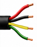
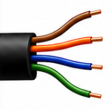
| Cable B | Spindle Cable | 4-conductor cable |
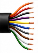
| Cable C | Gantry Cable | 10-conductor cable |
DWC Standard:
Input 1 Digital Probe is reference only and is not part of the Carousel ATC system.