Machine Compatibility
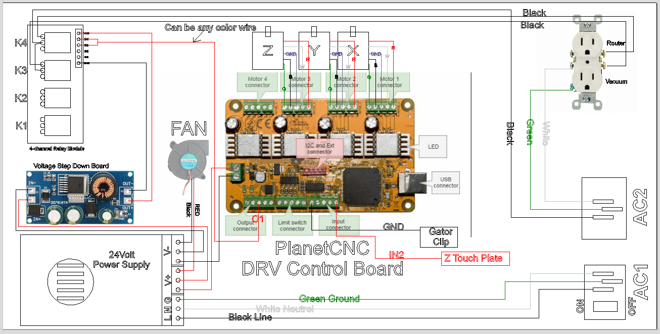
DWC1824 wiring configuration
| Item | Assignment | Notes |
|---|---|---|
| Machine | DWC1824 | Bench-top Digital Wood Carver CNC |
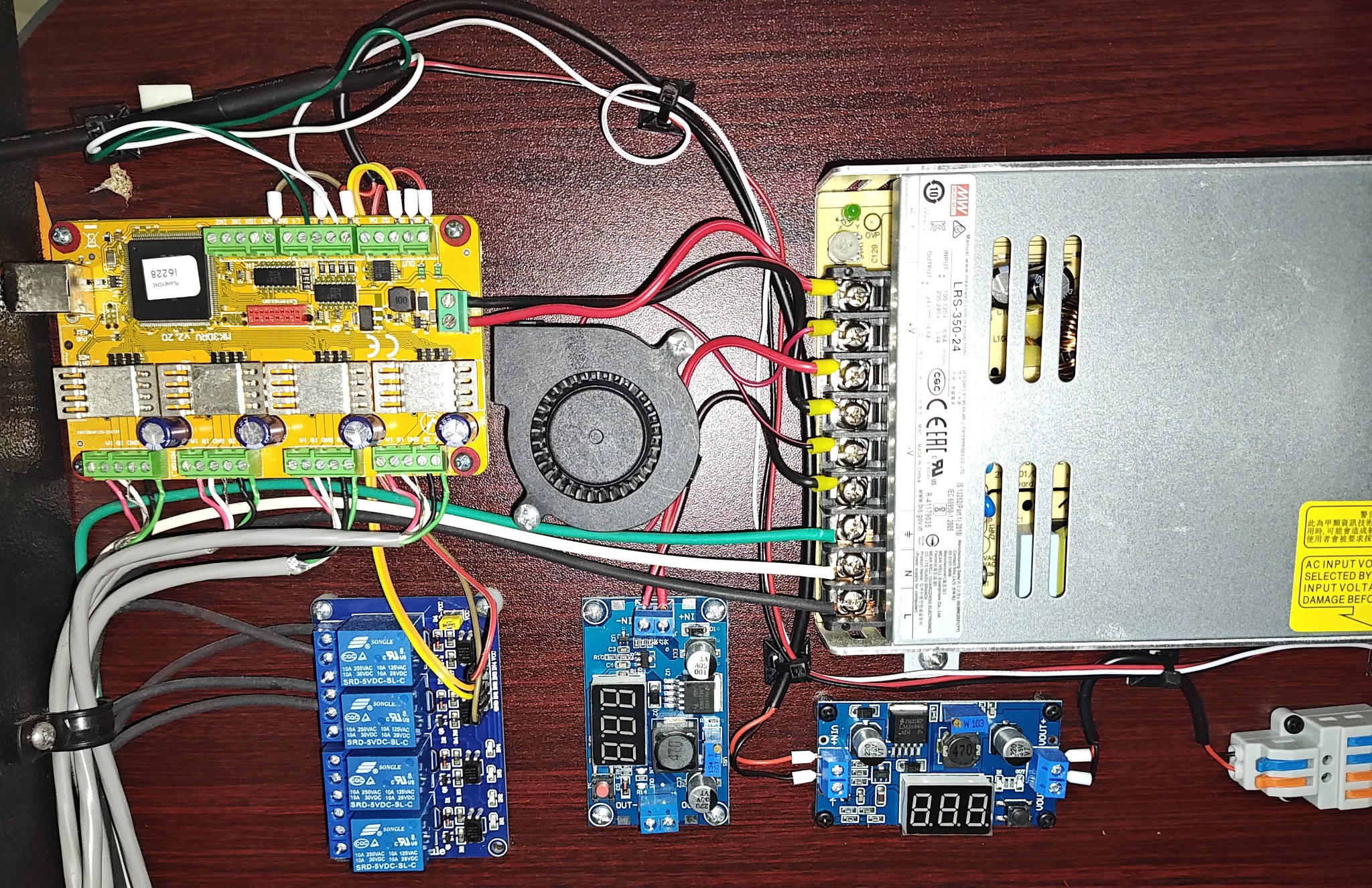
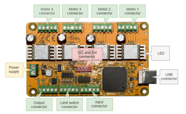
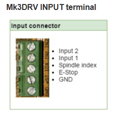
| Controller | PlanetCNC MK3DRV | Integrated driver controller platform |
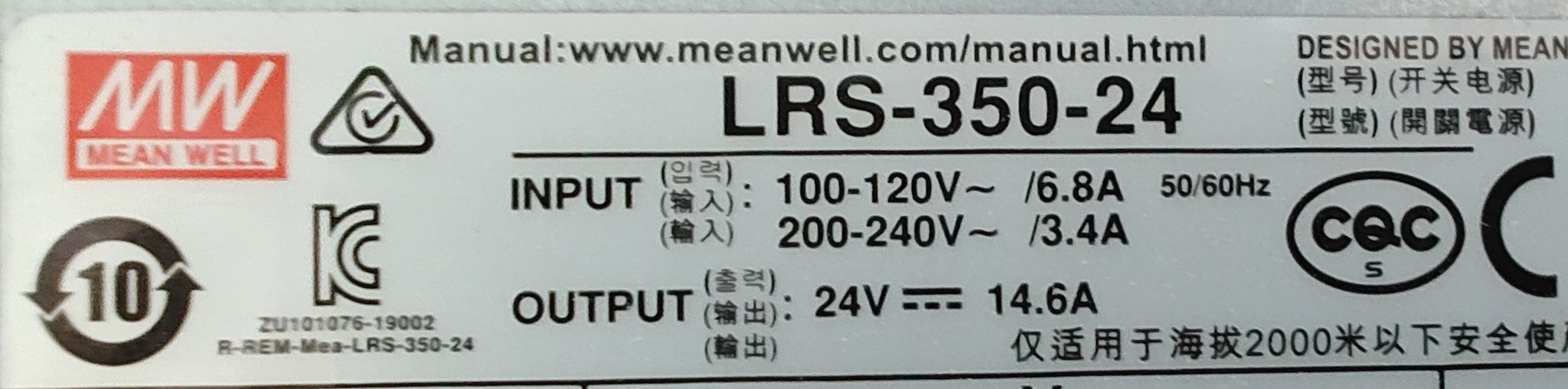
| Main PSU | Mean Well LRS-350-24 | 24VDC / 14.6A output |
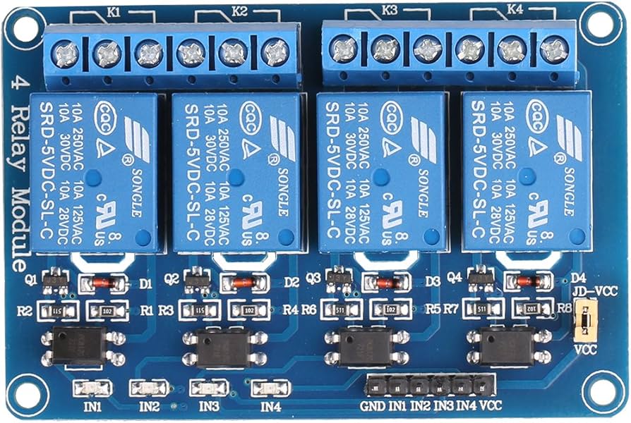
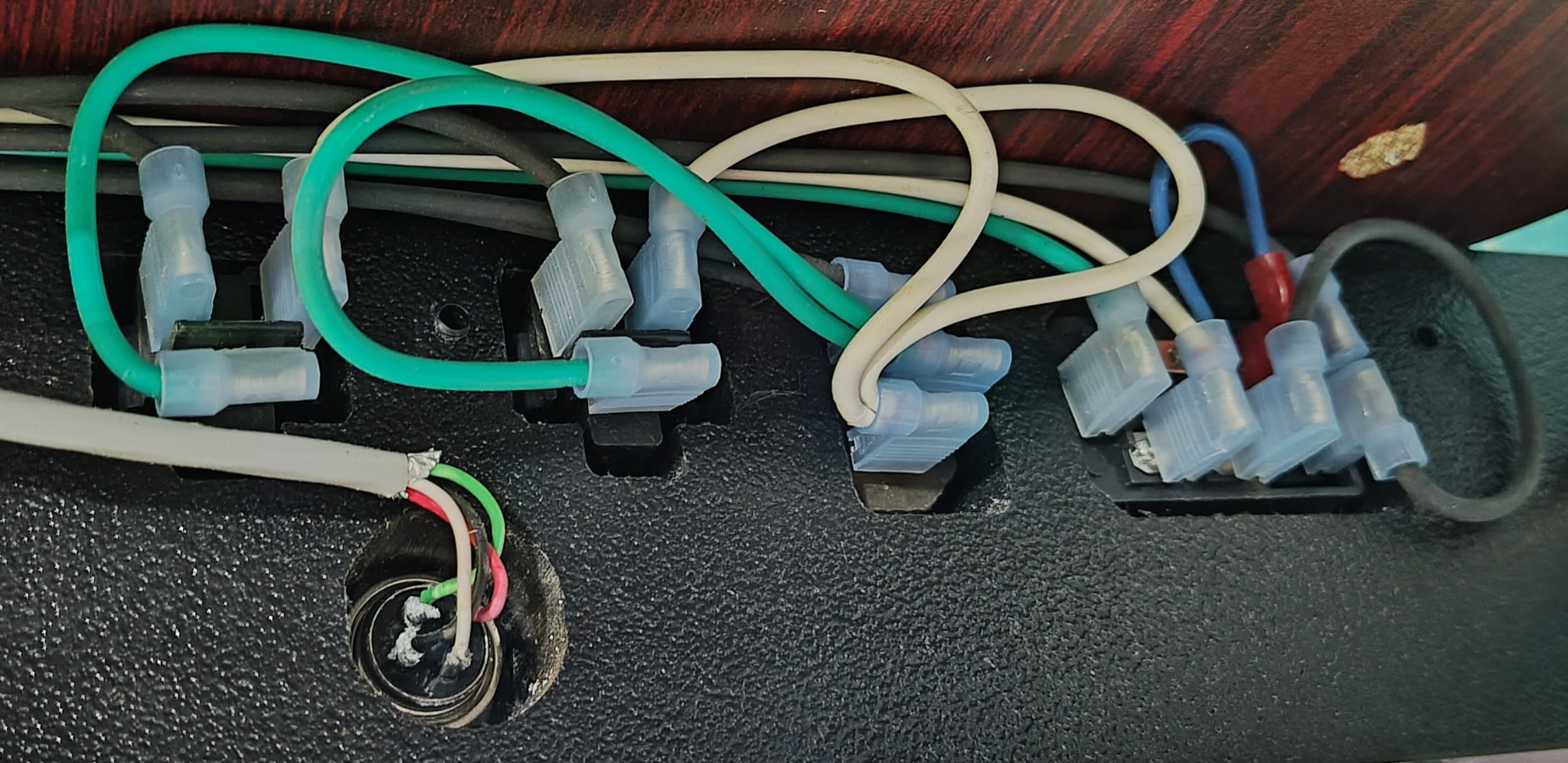
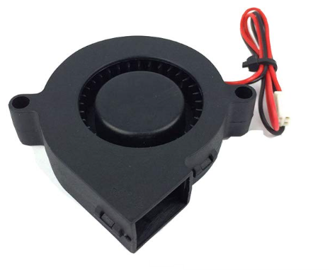
| Relay Module | 4-channel relay module | K3 = Vacuum, K4 = Router |
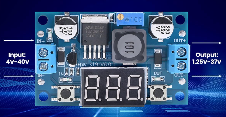
| Logic Supply | LM2596 Buck Converter | 24VDC input, 5VDC output to relay module |
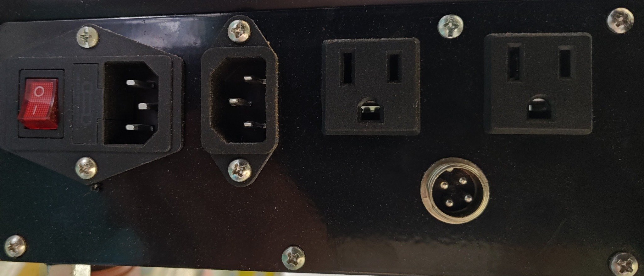
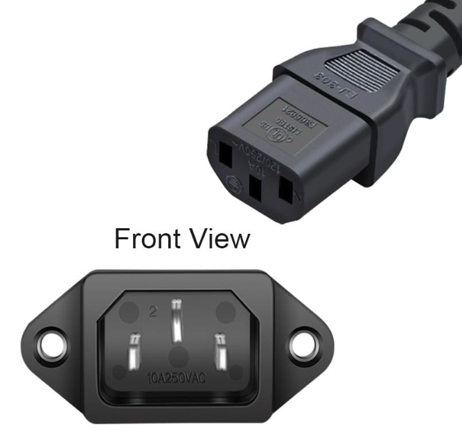
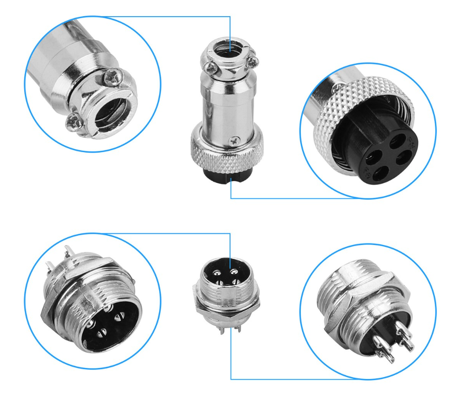
| Rear Rotary Port | 4-pin aviation connector | Connects to MK3DRV Motor 4 / A-axis |